
Over time I’ve noticed that most of the explanations of Fresnel reflection floating around the internet either barely touch on a decent explanation, are thorough but contain a lot of maths and code which is unnecessary for most artists, or are just flat out wrong. This is made particularly confusing when picking up a new package or render engine, as different packages allow you to drive Fresnel reflection with different parameters. For example:
- An Arnold user may be used to using a single value for “Reflectance at Normal” [1]
- A RenderMan user may be used to having RGB values for IOR and Extinction Coefficient [2]
- A Redshift user has access to versions of all of the above, PLUS a Reflectivity/Edge tint model [3]
- A Substance Designer/Painter user will be used to a black/white “Metalness” map [4]
With so many different options between packages, it’s easy to see how this can get confusing. Someone going from one package to another will probably have some intuition of what works and what doesn’t, but might feel limited with less control than they are used to, or overwhelmed by more than they are used to. Not fully understanding these parameters can lead to breaking physical accuracy and therefore less predictable results.
I’m going to attempt to give an explanation of Fresnel reflection which is not specific to any one package, and then explain how all of these different Fresnel reflection modes relate to each other, and how they differ. I will avoid getting in deeper into the maths, code or physics than is necessary for this purpose, but all of my references and further reading is included at the bottom.
What is Fresnel reflection?
Most people reading this will know that Fresnel reflection is related to the effect on specular objects (i.e most materials we create) where the parts of an object facing us are less reflective, and at grazing angles become more reflective. In fact, at a 90° angle from our eye/camera, all objects reflect 100% of light that hits them and act as a mirror. We can see this clearly in nature when looking at a flat body of water; the water further away from us is more reflective, whilst we can easily look right through the water closest to us. The effect is less noticeable on a rough ocean, where the viewing angle at each point is different – this is also why the Fresnel effect is less noticeable on rough objects. [5]
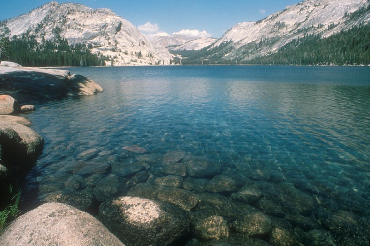 Tenaya Lake, Yosemite National Park
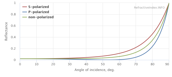
We can see the fact that 100% of light is reflected at 90° using measured data from refractiveindex.info – a database of different measured materials and their reflectance at different angles and wavelengths. Here is the reflectance of water from 0° to 90°, where the reflectance goes from about 2% to 100% (ignore S-polarised and P-polarised light, here we only care about non-polarised):
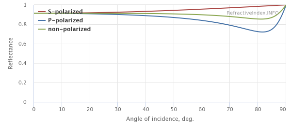
To prove that this is true for all objects, here is a completely different material, aluminium (note the very different response curve, metals react very differently but are still 100% reflective at a grazing angle):
So, why does this happen? When light moves from one medium to another, the light changes speed. Because light will always travel the shortest possible path, this change in speed causes the light to change direction. We describe the ratio of the speed of light from one medium to another as the index of refraction or IOR, mathematically noted as η (“eta”). In CG we almost always treat the first medium, the “air” as a vacuum. So in CG when we talk about IOR we are talking about the ratio of the speed of light in a vacuum to the speed of light inside the medium the light ray is entering. When this occurs, some of the light may be transmitted (refracted) into the medium; the smaller the angle of incidence (the angle between the viewer and the surface normal), the more light that gets transmitted. Due to the law of Conservation of Energy (the total amount of energy must remain constant), the rest of the light will be reflected, as the sum of transmitted and reflected light must be equal to the amount of incident light. [6]
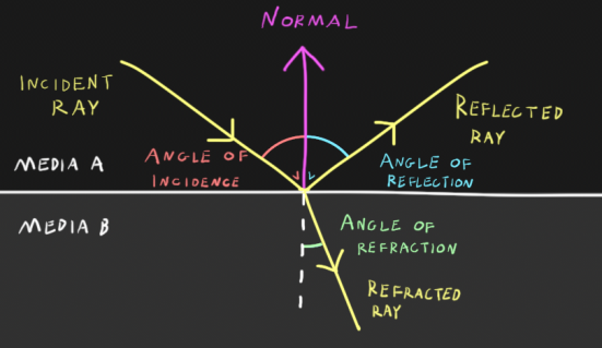
This proportion of reflected vs. transmitted light is given by the Fresnel intensity equations, and the amount of reflected light given by these equations is our Fresnel reflection. The Fresnel intensity equations take the angle of the incident ray to the normal of the surface and the refractive indices of both mediums as parameters and output the amount of light to be reflected and the amount of light to be refracted. From these parameters we can also calculate the angles of both reflection and refraction, however the angle of reflection is only dependent on the normal and angle of incidence, whereas refraction depends on the indices of refraction on top of this. Changing your IOR does NOT effect angle of reflection, but does effect angle of refraction. The angle of refraction is given by Snell’s Law which I won’t cover here, but I’ve included reference at the bottom – the only purpose of the Fresnel intensity equations is calculating the ratio of transmitted vs reflected light. [7]
IOR values for different transmissive media (top to bottom) – ice (1.31), crown glass (1.52), flint glass (1.8), and diamond (2.41)
Note how the reflections change in intensity but not shape, but the refractions do change shape
Some shaders do not use an IOR parameter for Fresnel reflections, and decide to use the possibly more intuitive concept of reflectance at facing-angle (this may come under different names such as “f0”, “reflectance at normal”, etc, but is equivalent in each). This gives the user control over what ratio of light is reflected at 0° from the camera (f0, or facing-angle), but does the exact same thing as adjusting the IOR. Just as adjusting the IOR will give us different reflectance values at the facing-angle, we can reverse this and figure out the IOR from the reflectance at the facing-angle – for example an IOR of 1.5 will give us a reflectance of 4%, and vice-versa. This is nice because it allows us to map with values between 0 and 1 (as we usually do with our textures), and has a more direct correlation to what we actually see in the shader.
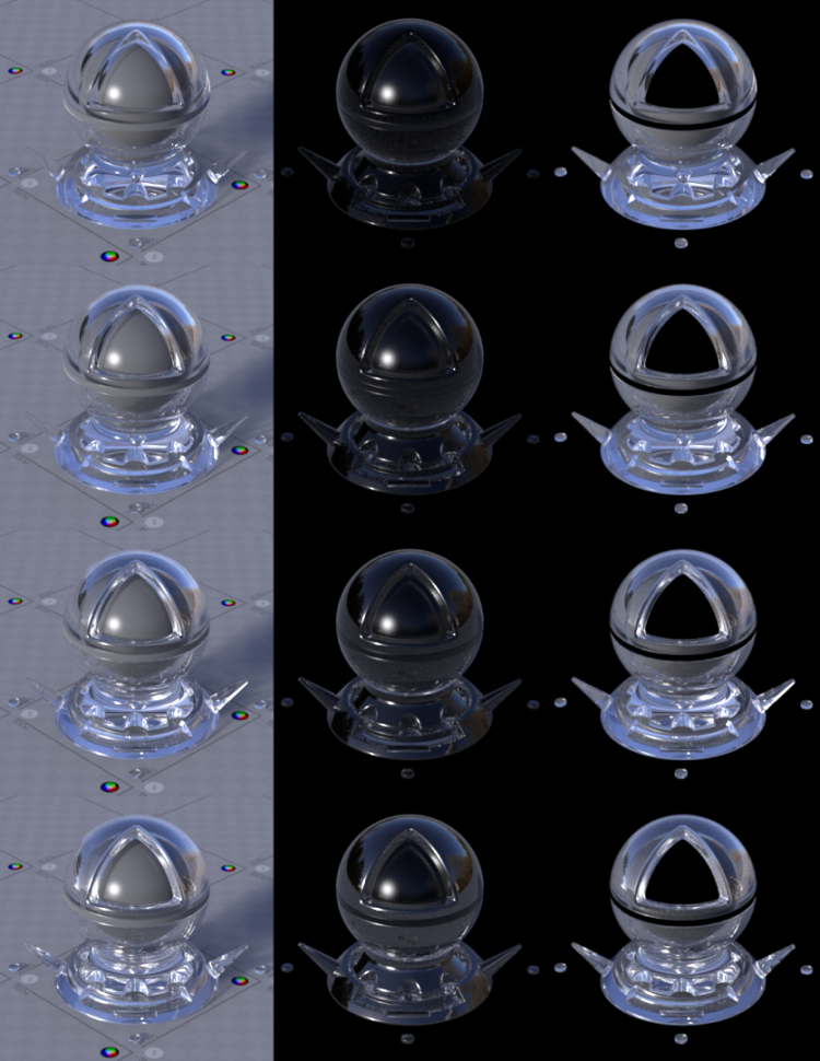
So, hopefully this is a complete enough description of the IOR parameter on many shaders. But, why do some of these shaders IOR parameters have RGB inputs? This is because the reflectance also depends on the wavelength. For dielectrics (non-metals), there is very little change due to wavelength, giving us achromatic reflections, so many shaders use a single value for IOR. However, for metals, we can sometimes get quite different responses at different wavelengths, which is what gives metals coloured reflections. Any Fresnel reflection mode using an RGB IOR will have another parameter, the extinction coefficient, and together they give us a metallic Fresnel curve. When using this mode, specular colour should not be tinted, as colour should come only from these two parameters – this is a much more physically accurate representation of metallic Fresnel as any Fresnel mode using just IOR is only capable of accurately simulating a non-metallic Fresnel curve.
This is where it gets complex…
When light enters a medium, not only may it be transmitted or reflected, but some of it may also be absorbed. Electrical conductors (i.e, metals) have very high absorption (or extinction) rates, so if light is transmitted rather than reflected, it is almost immediately absorbed. This is why metals are always opaque, and no subsurface scattering occurs. To account for this, we can add another parameter, the extinction coefficient. In our Fresnel intensity equations we can take our index of refraction and replace it with a complex index of refraction, η – iκ, where κ (“kappa”) is the complex part that accounts for extinction. If you don’t know what complex numbers are don’t worry as it isn’t important for this explanation, just know that complex numbers are a convenient way to encode the refractive index and extinction coefficient with a single value. This is what gives us the noticeably distinct reflectance curve in metals, with the characteristic dip right before it reaches 100% reflectance at 90°. Dielectrics will have an extinction coefficient of zero. [8]
The extinction coefficient parameter may not be familiar, because many shaders are designed to just take an IOR or “reflectance at facing angle” value. By using high values for either of these or turning Fresnel off and tinting the specular colour we can achieve a metallic look which is often satisfactory. However, the response curve will not exactly match that of an actual, measured metal.
Gold without Fresnel reflections + tinted spec and with RGB IOR + Extinction Coefficient – note the shifts in intensity and colour at glancing angles
Another alternative to this is the Reflectivity / Edge Tint model – two RGB parameters, Reflectivity for reflectance at facing-angle, and Edge Tint to describe the change of colour at grazing angles. This is just a remapping of IOR / extinction coefficient to more intuitive parameters, therefore you can use physically correct colour values to get results that match measured data. This might be preferable because rather than having to copy values from a database or guess at less obvious parameters like extinction coefficient, you can paint maps with artistic / guessed values and still have metals that react with that characteristic metallic Fresnel curve. For dielectrics, Edge tint is simply left black, and Reflectivity uses achromatic values.
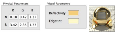
As mentioned earlier, metals have different responses at different wavelengths, but how this relates to an RGB colour might not be very clear. Calculating these RGB values requires calculating a spectrum and doing multiple conversions based on a colour profile, which is outside of the scope of this lesson. However, it is possible to roughly approximate Reflectivity and Edge Tint by going to refractiveindex.info, entering 0.65, .55 and .44 µm (micrometre) wavelengths for red, green and blue respectively, and using the values given by the reflection calculator for R (non-polarised) at 0° incidence for Reflectivity, and 80° for Edge Tint. Again, this is just a vague approximation, and accurate results require spectral calculations. [10]
Metallic
Common in real-time PBR engines, the metallic or metalness parameter is used to simplify Fresnel for artists, whilst also allowing for optimisation in real-time rendering. However, this parameter is also seen in offline renderers. As metals tend to have little to no diffuse component and dielectrics have grey reflections, we can use a single colour, often called “base color” for our materials. For metallic surfaces the “base color” is used for reflectivity at facing-angle (in game engines often called specular color), and for dielectrics it is used for diffuse colour. Often for dielectrics there is limited control over the IOR – for example, Substance Designer allows for a small range of adjustment, and Painter uses an IOR of 1.5 for all dielectrics. Often this is fine because the range of IOR for dielectrics is quite limited, from about 1.33 to 2, or 2% reflectivity at facing-angle to 11%, but usually hanging around 1.5 IOR. However to get an accurate representation this makes a big difference so it is worth playing with if you have the option. This model is often paired with the Fresnel Schlick approximation, a cheaper approximation of Fresnel that introduces some error but works well for standard dielectric values. [8] [11] Note that metallic maps should be black and white, with grey values only used for anti-aliasing. For example, grey values are acceptable in areas where the microsurface has both metallic and non-metallic areas within one pixel and we don’t have the required resolution to separate them, as opposed to a material that is somewhere in between the two.
So, there it is – a lot of different set-ups, but I believe understanding how specular Fresnel works and what your parameters are doing it should make it much easier to achieve the look you want without too much guesswork. Thanks to Vincent Dedun for proofreading this for me and helping to remove some embarrassing mistakes 🙂
References and Further Reading
[1] https://support.solidangle.com/display/AFMUG/Specular
[2] https://rmanwiki.pixar.com/display/REN/PxrSurface#PxrSurface-SpecularandRoughSpecularParameters
[3] https://docs.redshift3d.com/display/RSDOCS/Material?product=maya#Material-Reflection
[4] https://academy.allegorithmic.com/courses/b6377358ad36c444f45e2deaa0626e65
[5] https://www.scratchapixel.com/lessons/3d-basic-rendering/introduction-to-shading/reflection-refraction-fresnel
[6] https://en.wikipedia.org/wiki/Refractive_index
[7] https://en.wikipedia.org/wiki/Snell%27s_law
[8] https://seblagarde.wordpress.com/2013/04/29/memo-on-fresnel-equations/
[9] https://groups.google.com/forum/#!topic/alshaders/IZTbaqJMQBo
[10] http://jcgt.org/published/0003/04/03/paper.pdf
[11] https://disney-animation.s3.amazonaws.com/library/s2012_pbs_disney_brdf_notes_v2.pdf
